MSTKN modular tool holder system
The devices that make up the MSTKN system comprise a combination of two different basic elements. These are combined with each other in various ways and are integrated into different types of housing. The system’s basic elements are:
- Gateway element: Gateway elements establish the connection between a field interface (eg fieldbus interface) and the internal bus system. Gateway elements are available for 24V I/O and for various fieldbus systems (PROFIBUS-DP, PROFINET, ethernet/IP, IndraLogic CAA etc) and establish the connection between the tool holder system and the overriding process control (ie the screwing system).
- Sensor element: Sensor elements contain sensors that are able to detect the presence of tools in the appropriate rack, and which then record their presence via the internal bus system. Sensor elements are available in different designs (number of sensors, large/small sensors for different types of tools) and different technologies (for detecting when tools are present or in use, but also for tool identification purposes).
These elements are combined to make the following MSTKN system devices:
- Main module (HM): A main module combines a gateway element with one or more sensor elements and is built into one of the MSTKN system housings. A main module is a standalone, fully functional tool holder that can be connected directly to a PLC or screwing system. Expansion modules can be connected to a main module via the internal bus system, thus increasing the total number of tools that can be monitored.
- Expansion module (EM): An expansion module comprises one or more sensor elements, and is built into one of the MSTKN system housings. Expansion modules need to be connected to the MSTKN system’s internal bus system, either via a gateway module or a main module.
- Gateway module (GM): A gateway module consists of a gateway element, built into the housing for the control cabinet (mounting rail housing). The gateway module enables one or more expansion modules to be connected to a 24V I/O interface or a fieldbus system.
The devices that make up the MSTKN system comprise a combination of two different basic elements. These are combined with each other in various ways and are integrated into different types of housing. The system’s basic elements are:
- Gateway element: Gateway elements establish the connection between a field interface (eg fieldbus interface) and the internal bus system. Gateway elements are available for 24V I/O and for various fieldbus systems (PROFIBUS-DP, PROFINET, ethernet/IP, IndraLogic CAA etc) and establish the connection between the tool holder system and the overriding process control (ie the screwing system).
- Sensor element: Sensor elements contain sensors that are able to detect the presence of tools in the appropriate rack, and which then record their presence via the internal bus system. Sensor elements are available in different designs (number of sensors, large/small sensors for different types of tools) and different technologies (for detecting when tools are present or in use, but also for tool identification purposes).
All components of the MSTKN system can be combined, as they all communicate with each other via the same internal bus system. A tool holder system should always contain a gateway element and at least one sensor element, regardless of the design, housing type or sensor types being used.
variants
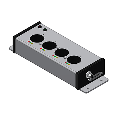
tool holder 4fold from 1/4" - 3/4"
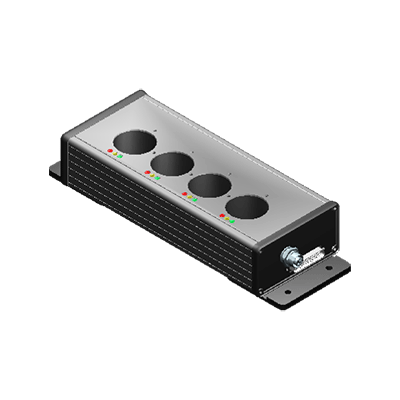
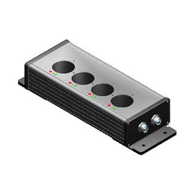
tool holder 4fold for 1"
- Aluminium housing L x B x H, 250 x 103 x 53mm
- Main module expandable
- Connection round plug M12 24V digital I/O
- Status display each tool slot via 3 LED`s
- Tool holder for 4 Sockets to Ø35mm
- Aluminium housing L x B x H, 440 x 160 x 115mm
- Tool holder with integrated mistake proof
- Connection round plug M12 24V digital I/O
- Status display each tool slot via 3 LED`s
- Tool holder for 4 Sockets to Ø35mm
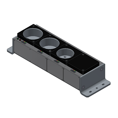
inserts for assembly tools
mechanical differentiation
By the size of the hole diameter and an additional bolt in the middle of the lcation hole the tool can be assigned to the slot.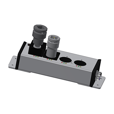
Electrical differentiation
The Changing of the magnetic field on the sensor of the slot is measured. That can be affected by using different materials (placing an aluminium sleeve).The assignment or the limit of the sensor measurement to the slots is teached via a PC.
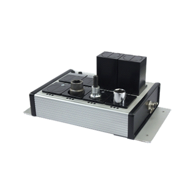
device types
main module
- (sensor element + gateway element)
expansion module
- (sensor element only)
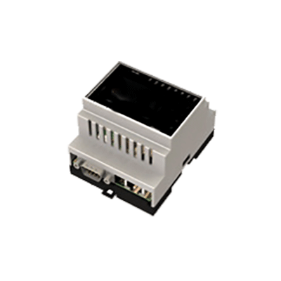
gateway module
- (gateway element only)
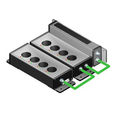
- combination of various housing types possible
- common internal bus system connects all components
- up to 8 modules and 64 slots (31 for 24V-E/A variant) possible
- for Field bus versions a division is possible (for example left and right)
operation modes
Der Stecknussköcher unterstützt folgende Betriebsarten:
- Freie Auswahl: Es steht dem Werker frei, welche Nuss er aus dem Köcher entnimmt. Die Steckplatznummer des entnommenen Werkzeugs wird über die Feldbus Ausgangssignale angezeigt. Entnimmt der Werker mehr als ein Werkzeug, wird über die Schnittstelle ein Fehler ausgegeben. Die Leuchtdioden am Stecknussköcher dienen zur Zustands- bzw. Fehleranzeige und zur Anzeige, ob die Entnahme korrekt ist (Fehleranzeige, falls z. B. mehr als ein Werkzeug entnommen wurde). Um den Köcher in dieser Betriebsart zu betreiben, müssen alle Eingänge des MSTKN „0“ sein.
- Werkerführung: In dieser Betriebsart gibt eine externe Steuerung (z.B. Schraubersteuerung oder SPS), über die Feldbus-Schnittstelle vor, welches Werkzeug entnommen werden soll. Der Stecknussköcher zeigt dies durch die Leuchtdioden der einzelnen Steckplätze an. Bei Entnahme eines Werkzeugs meldet der Köcher den Zustand an die externe Steuerung und setzt, bei korrekter Entnahme (Entnahme identisch mit Vorwahl), ein Freigabebit. Der Zustand der Leuchtdioden ändert sich bei korrekter Entnahme von grün blinkend zu einem grünen Dauerlicht. Bei Falschentnahme leuchtet die rote LED auf. In der Standardvariante kann die Steuerung nur ein Werkzeug vorwählen, in der Variante Open Protocol ist es möglich, den Werker eine Auswahl aus mehreren Werkzeugen zu erlauben („Bitmuster“).
- Direktbetrieb: Diese Betriebsart arbeitet ähnlich wie die Betriebsart „Freie Auswahl“, ist aber um eine Überwachungsfunktion erweitert, die zur Erkennung von Kurzschlüssen und nicht verbundenen Leitungen dient. Der Stecknussköcher sendet je nach Status sein Ausgangssignal an die Steuerung und erwartet dieses, innerhalb von ca. 150ms, als Eingangssignal zurück. Erst danach erfolgt das Setzten des Freigabebits durch den Stecknussköcher. Erhält der Stecknussköcher nicht den korrekten Wert zurück (Ausgangssignal ≠ Eingangssignal), wird das Freigabebit nicht gesetzt und über die Leuchtdioden wird ein definiertes Leuchtmuster ausgegeben.
- Diagnose- und Konfigurationsbetrieb: Je nach eingesetztem Gerätetyp werden verschiedene Betriebsarten zu Diagnose- (z.B. Kabelbruch Test) und Konfigurationszwecken (z.B. Sensorkalibrierung) unterstützt. Bitte entnehmen sie die detaillierte Beschreibung den nachfolgenden Erklärungen.
- Intelligenter Betrieb: Diese Betriebsart findet bei den Feldbus Varianten (Profibus, Modbus UDP etc.) ihren Einsatz. Mit dieser Einstellung übernimmt der Stecknussköcher sowohl die Steuerung der LEDs, als auch die Auswertung der Steckplatzzustände in Verbindung mit der getroffenen Vorwahl.
- Benutzer Betrieb: Auch diese Betriebsart ist nur bei den Feldbus Varianten von Bedeutung. In dieser Betriebsart übernimmt der Nutzer die vollständige Steuerung und Auswertung der Stecknussköchersignale. D.h. der Nutzer kann beliebige Leuchtdiodenmuster generieren und z.B. Mehrfachentnahmen erlauben.